We are gonna show you how to install Spoiler for Mclaren 570S step by step ,usually 570GT is different design and installation but today we are talking about 570S
Professional install is highly recommended!
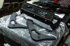
Step 1) On the driver side door, locate the engine cover release button and press it (TOP BUTTON)
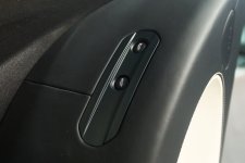
Step 2) Remove the two 4mm Allen head screws
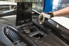
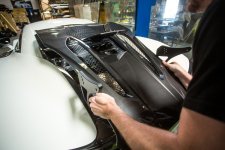
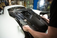
Step 3) Next remove the engine cover carefully by grabbing each side of the engine cover and lifting upwards at the rear of the engine cover, with the engine cover slightly tilted upwards, slide the cover gently a few inches back towards the rear of the vehicle to free from the rubber grommets. Once free from the grommets you can lift the engine cover up and out of the vehicle. Use the photos provided below for reference.
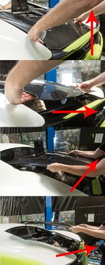
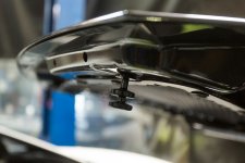
Here are images for reference showing the the mounting tabs on the engine cover.
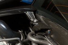
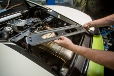
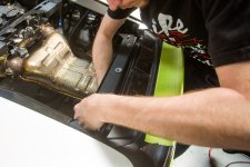
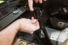
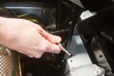
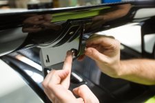
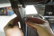
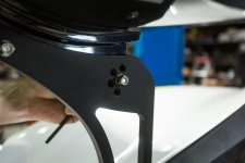
Step 5) Remove the (8) bolts located on the inside of the side support brackets. Use Images below for reference.
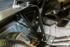
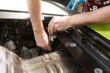
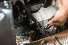
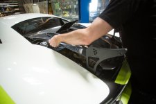
Step 6) Remove the (3) bolts located on the underside of the upper support bracket. Remove only the inner (3) bolts that run horizontal across the underside of the upper support bracket. This will allow you to remove the entire bracket assembly as one piece. Use images below as reference.
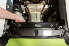
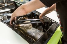
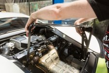
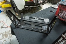
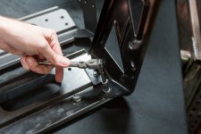
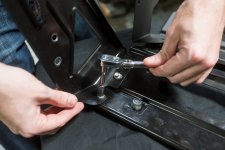
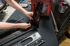
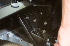
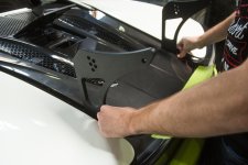
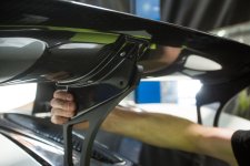
Step 8) Remove the (6) bolts securing the side support brackets to the upper support bracket. Once removed, swap the side support brackets over to the new Agency Power Upper Support Bracket. Use images below as reference.
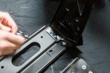
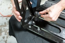
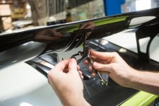
Step 9) Remove the 3x rubber grommets and reinstall onto the new Agency Power Upper Bracket as shown.
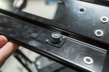
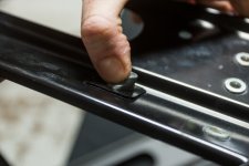
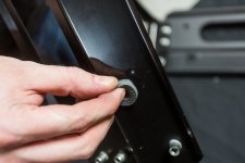
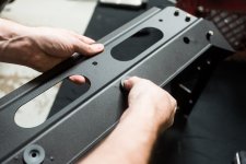
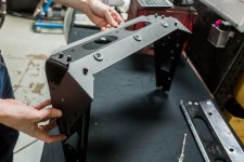
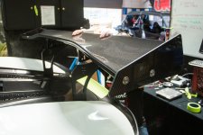
Step 10) Re-install the Agency Power Wing Bracket Assembly using the existing OEM hardware.
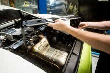
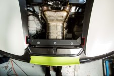
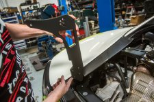
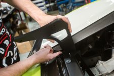
Step 12) Test fit the wing upright and re-trim if necessary.
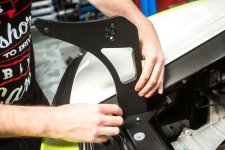
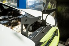
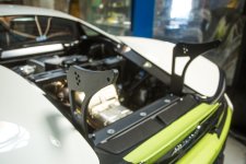
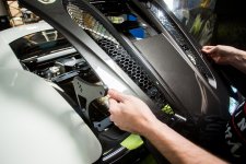
Step 14) Next re-install the engine cover by carefully guiding it past the uprights. Use the provided images below for reference.
Professional install is highly recommended!

Step 1) On the driver side door, locate the engine cover release button and press it (TOP BUTTON)

Step 2) Remove the two 4mm Allen head screws

Step 3) Next remove the engine cover carefully by grabbing each side of the engine cover and lifting upwards at the rear of the engine cover, with the engine cover slightly tilted upwards, slide the cover gently a few inches back towards the rear of the vehicle to free from the rubber grommets. Once free from the grommets you can lift the engine cover up and out of the vehicle. Use the photos provided below for reference.

Here are images for reference showing the the mounting tabs on the engine cover.


Step 5) Remove the (8) bolts located on the inside of the side support brackets. Use Images below for reference.


Step 6) Remove the (3) bolts located on the underside of the upper support bracket. Remove only the inner (3) bolts that run horizontal across the underside of the upper support bracket. This will allow you to remove the entire bracket assembly as one piece. Use images below as reference.


Step 8) Remove the (6) bolts securing the side support brackets to the upper support bracket. Once removed, swap the side support brackets over to the new Agency Power Upper Support Bracket. Use images below as reference.


Step 9) Remove the 3x rubber grommets and reinstall onto the new Agency Power Upper Bracket as shown.


Step 10) Re-install the Agency Power Wing Bracket Assembly using the existing OEM hardware.


Step 12) Test fit the wing upright and re-trim if necessary.


Step 14) Next re-install the engine cover by carefully guiding it past the uprights. Use the provided images below for reference.


Last edited:
